Product Description
POWERPACK® CONTENTS
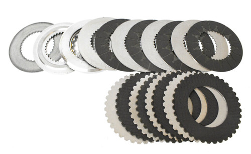
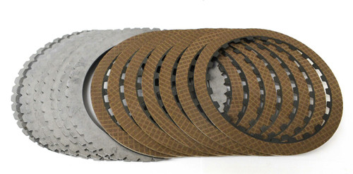
- (8) 152700D170 (.067”) G3 1-Sided Internal Spline Friction Plates
- (8) 152701D170 (.067”) G3 1-Sided External Spline Friction Plates
- (1) 152761P115 (.450”) Top Pressure Plate
- (1) 152766 (.103”) Bottom Apply Plate 1999-2005
- (1) 152701-218 (.086”) Bottom Apply Plate 2006-On
POWERPACK® 152755B, 1999-2005 INSTALLATION
Install the apply plate 152766 (.103”) against the apply piston. Install externally splined friction with the friction lining facing down (away from you). Alternate installation of internally splined plates and externally splined plates ending with an internally splined plate. (8 external & 8 internally splined plates)(Failure to install plates correctly will result in catastrophic failure; steel sides of friction plates must never make contact with each other). Install top pressure plate 152761P115 and snap ring. (Do not install spiral ring at this time). Check clutch pack clearance should measure .075” (1.90mm) to .085” (2.15mm). If clearance is incorrect, pressure plates are available from Allison. When correct C1 clutch pack clearance is achieved, install spiral ring.
POWERPACK® 152755B, 2006-on INSTALLATION
Install the apply plate 152701-218 (.086”) against the apply piston. Install externally splined friction with the friction lining facing down (away from you). Alternate installation of internally splined plates and externally splined plates ending with an internally splined plate. (8 external & 8 internally splined plates)(Failure to install plates correctly will result in catastrophic failure; steel sides of friction plates must never make contact with each other). Install top pressure plate 152761P115 and snap ring. (Do not install spiral ring at this time). Check clutch pack clearance should measure .075” (1.90mm) to .085” (2.15mm). If clearance is incorrect, pressure plates are available from Allison. When correct C1 clutch pack clearance is achieved, install spiral ring.


